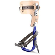


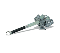


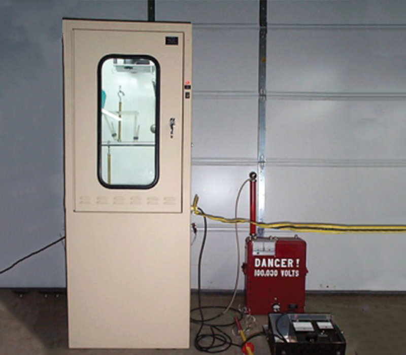
GM Series Glove-Sleeve Testing Accessory
Manual Testing of lineman’s glove and sleeves
Up to 100,000V DC with C-1 test set
Allows Testing to ASTM D120 and F496 Standards
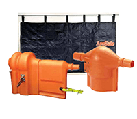
The GM022 is The VON Corporation’s most economical glove and sleeve tester. Units allow testing of Gloves and Sleeves. All standard rubber goods can be tested, even class IV. All machine adjustments are controlled manually, allowing maximum flexibility for low volume applications. A GM024 and GM026 are available with 4 and 6 glove capacities respectively.
The GM022 will manually test one or two lineman’s gloves or sleeves. The center to center spacing is 9 inches to accommodate 40 K.V. gloves.
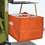
GLOVE TESTING: The one piece slave will simultaneously test one or two lineman’s gloves or sleeves which connected to a high voltage D.C. supply such as the VON Model C-1. The center to center spacing is 9 inches to accommodate Class IV gloves which are tested at 70,000 volts D.C. Clothespin type holders are provided which do not pinch the gloves. The same holders are used for testing both straight and curved sleeves.
SLEEVE TESTING: The machine is capable of testing all standard sleeves using the sling method, the hammock method, and with additional accessories by the straight method using a dielectric liquid in accordance with the latest ASTM D1051 and F496 standards. The tank is 22 inches deep so that the dielectric liquid can be left in the tank when testing 18 inch gloves. The tank is 26″ long so that 2 curved sleeves can be tested simultaneously by the straight method. One sleeve can be tested by the hammock method.
VOLTAGE: The input voltage is 120 volt 60 hertz A.C. single phase 10 amps for the blowers and the motor operated automatic grounding system. A shielded high voltage RG-8U lead is provided to connect to the external HV power supply. The test voltage is raised and lowered by the operator turning the variable autotransformer at the specified rate of approximately 3 kilovolt D.C. a second. Fault detection and current metering is provided by the external power supply.
HIGH VOLTAGE TEST TANK: The tank is constructed of stainless steel for corrosion protection. A valve is provided in the bottom of the tank to drain the water to clean the tank. The tank is filled to the proper level. Using a pitcher, water is taken from the tank to fill the gloves and put back in at the end of the test.
VENTILATION: 100 cfm of air flow is directed toward the gloves/sleeves to help dry any water that spills on the gloves and to prevent the water drops from going up the glove at 70kv. An exhaust fan in the rear of the cabinet pulls air across the surface of the water.
ENCLOSURE: The unit consists of a free standing cabinet 30″ wide x 22″ deep x 79″ tall. The loading door is interlocked with a motor operated resistive discharge device.
OPERATION: The operator opens the hinged loading door to remove a clothes pin and electrode assembly from the high voltage bus. He checks to see if the clothes pins are fastened to electrode in the position that will give the proper cuff to water line distance for the test voltage. He adjusts the cuff to water line distance by changing the location of the clothes pins on the electrode using the thumbscrew adjustment. He then hangs the glove by the clothes pins. The glove with its clothes pin and electrode assembly is hung on the HV bus. Water is then taken from the test tank and put into the glove until the inside is filled to the correct water level using a plastic pitcher. Then a glove is loaded into the second clothes pin and electrode assembly. When testing only one glove, the second clothes pin and electrode assembly may be hung from a hook in the upper right corner of the unit.
After loading the gloves or sleeves, the operator closes the loading door. The limit switch turns on the blower and operates the solenoid which removes the resistive ground from the HV bus.
The operator then moves to the external HV supply and removes its discharge device. The external supply is turned on and the voltage raised to the desired test level by turning up the autotransformer. After timing the test, the voltage is lowered by the operator. If a glove fails the external power supply circuit breaker will trip out. The faulted glove can be determined by running the power supply up until there is high but steady current and looking into the viewing window to determine the faulted glove by the bubbles created at the fault. The faulted glove can also be determined by removing one glove and checking each glove individually.
| Number of Gloves/Sleeves | |
| GM-022 | 2 |
| GM-024 | 4 |
| GM-026 | 6 |