TVM Series Live Line Tool (Hot Stick) Testers
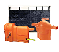
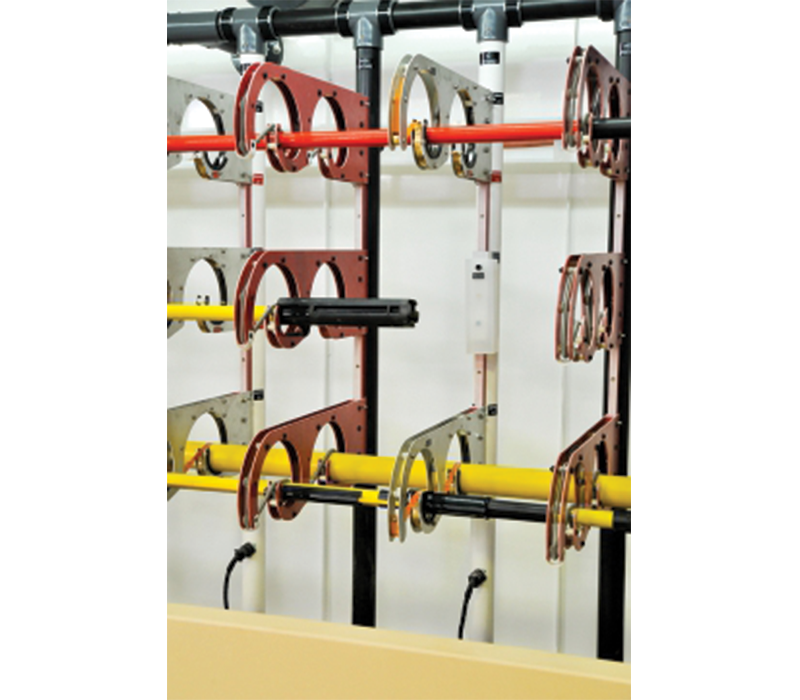
Innovative Electrodes automatically wrap stick during loading
Guarded Current Metering allows AC Testing by Leakage Current
Up to 100,000V AC or 100,000V DC per foot
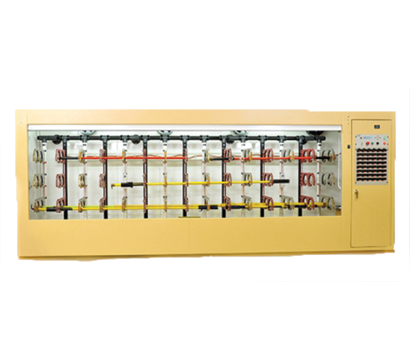
Allows Testing to IEEE 978 and OSHA Regulations The TVM Series is The VON Corporation’s fully automated live line tools (hot stick) test solution. Units allow testing of all standard live tools to meet IEEE 978 and current OSHA regulations.
Tests are timed and an audible alarm sounds failures or test complete, with bright flashing colored lights signaling which position failed or test complete.
CAPACITY: The TVM machine will automatically and simultaneously test six 14 foot sticks at voltages to 100,000 volts A.C. or 100kV DC, depending on purchased options (80kV AC and/or 100kV DC Standard).
VOLTAGE: The input voltage is 120/240 volt A.C. single phase. The TVM series has 0-80,000 volts or 0-100,000 volts A.C. test voltage provided by a continuous duty transformer. The TVM-DC series has 0-100,000 volt D.C. supply. The test voltage is measured by means of a resistive divider connected directly across the high voltage circuit. An LCD diplays the output voltage both digitally and with a bar graph. The test voltage is raised and lowered with a special solid state device at a rate of approximately 3 kilovolts per second.
CURRENT: High Voltage and Return Current positions are alternated every 1 foot. The current of each section being being tested is continuously monitored by the microprocessor control system. The active current leakage is displayed on an LCD display both digitally. A special guard system is used to eliminate capacitive currents when testing with AC, allowing microampere level current measurements of the resisitve current through the stick. This allows testing to meet IEEE 978 in a minimum one minute test, without resorting to the 5 minute heating test. Additionally, there is a circuit to check for a short circuited electrode.
VENTILATION: One exhaust fan is provided in the top rear of the blanket testing cabinet to remove ozone.
ENCLOSURE: Eyebolts are provided in the top for lifting by a crane.
CONTROLS: A menu based system provides all controls from the front control panel. All standard tests come predefined for the user. These predefined tests set all the machines settings and automatically run the test on the live line tool. There are also 4 user defined test modes available, as well as a mode for manual control of the entire system.
INDICATORS: All LED light indicators operate in a fail safe mode by being lighted at all times while active. The lights flash when indicating. A red “HIGH VOLTAGE FAILURE” light is provided on each current measurement point. A red ” FAIL” light and a green “TEST COMPLETE” light are provided on the control panel. The LCD current display shows the current leakage current, as well as saving the peak current. After a failure the LCD display also indicates which position failed.
OPERATION: The sticks are loaded into the tester. The act of loading the sticks wraps the electrode around them. Care must be taken around metallic hardware, to prevent flashovers. Insulation of hardware, or removal of electrode positions may be required, depending on the sticks loaded and their hardware. The operator selects the test setting from the menu, and pushes the “START” button.
The automatic high voltage cycle includes raising and lowering the voltage to the setpoint, automatic timing of the test, and automatic visual and audible indication of pass or fail. A stick which fails will stop the test, cause a steady audible signal, indicate which position has failed, and discharge any remaining voltage. A red flashing light is provided both at the current meter and at the position which failed, to allow quick determination of the failed portion.


