


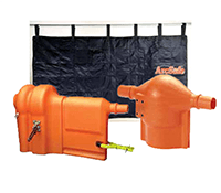


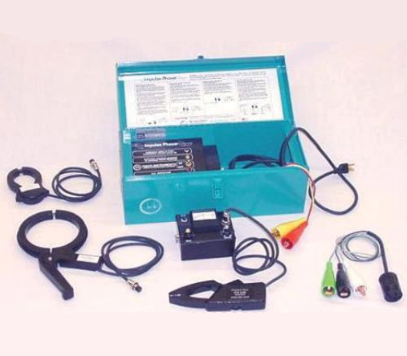
Cable Identification System and Cable Phasing System
Cat. No. 541001-10; -20; -30
The IMPULSE PHASER was originally developed in early 1950 to increase personal safety when working on paper insulated, lead covered cables. Since its introduction, the IMPULSE PHASER has been used safely and reliably by electric utilities throughout Canada and the U.S.
With the introduction of direct buried, solid dielectric primary voltage cables, the IMPULSE PHASER has come into greater prominence for safely and accurately identifying buried primary cables, including jacketed neutral designs. The IMPULSE PHASER has been accurately used on paper insulated, lead covered feeders in excess of 20 miles and even on submarine cable 300 feet underwater.
Simple operating procedure
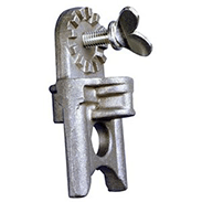
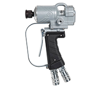
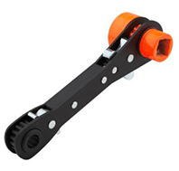
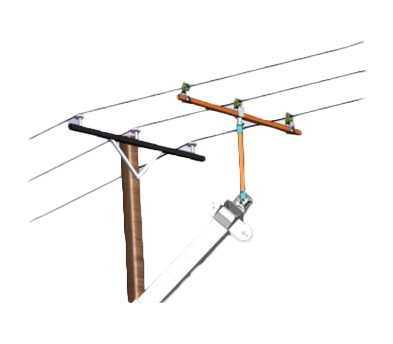
The first step in identifying a feeder circuit with the IMPULSE PHASER is to de-energize and ground the circuit. The IMPULSE PHASER transmitter is attached at one end of the feeder, the transmitter grounds are removed and the transmitter is turned on. Once the IMPULSE PHASER transmitter is connected and indicates it is operating properly, there is no need to remain with it. At the location where the cable is to be identified, the clamp-on is attached to the detector and the cable or phase is then identified using the color coded detector meter- it’s as easy as that.
Identification of direct buried primary cable is just as easy. De-energize and ground the cable between the two pad mounted transformers. In one of the transformers, on the cable to be identified, ground the conductor to all of the neutral conductors in the transformer. At the other end, connect the IMPULSE PHASER transmitter red “A” phase lead to the conductor to be identified. Connect the yellow “B” phase lead to all of the commonly connected neutrals and turn the IMPULSE PHASER on. At the open trench, use the clamp-on around each cable to obtain a meter deflection. One of the cables will give a red “A” phase meter deflection – that’s the cable to be worked on.
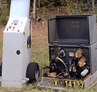
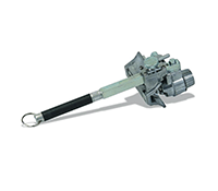
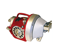
Transmitter Specifications:
Output Voltage: 95-100 V.D.C. (nominal)
Output Power: 5 joules @ 10 Amps (nominal)
Output Pulse Rate: 30-36 pulses per minute
Power Source: 120 volts A.C. @ 60 Hz. or 12v sealed battery
Controls: Red A.C. Indicator On/Off toggle switch Red and amber indicator lamps
Connections: 9′ A.C. cord for A.C. operation; 8′ Red & Yellow output hookup cables.
Weight & Dimensions: 15 lbs. 16″ x 7 1/2″ x 7″
Total Weight: 17 lbs. with all components stored in the transmitter case and tray.
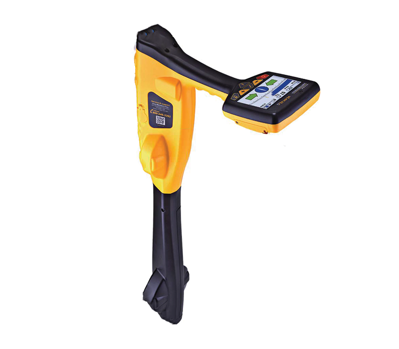
Detector Specifications:
Power Source: 9v Alkaline transistor battery
Controls: Momentary contact “ON” switch Meter zero control knob Signal sensitivity control knob
Connections: 4 Pin microphone jack
Weight & Dimensions: 1 lb. 5 3/4″ x 3 5/8″ x1 3/4″